
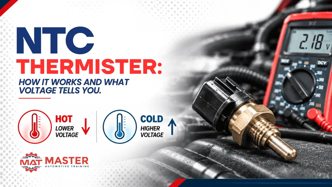
NTC Thermistor: How It Works and What Voltage Tells You
NTC thermistor. Sounds like a candy wrapper.
It isn’t. It’s the sensor sitting behind almost every temperature reading on the car — coolant, intake air, fuel, evaporator core. And most techs know the abbreviation without knowing what’s actually happening in the circuit, or why the scan tool reads high voltage when the sensor is cold and low voltage when it’s hot.
Here’s the whole picture. Once you see it, you’ll know how every NTC thermistor in the vehicle works — because they all work the same way.
1. What NTC Actually Stands For
NTC stands for Negative Temperature Coefficient. The whole behavior of the sensor is in the name.
- As temperature rises, resistance falls.
- As temperature drops, resistance rises.
Inverse relationship. Always. That single rule is the foundation for everything else in this post — including why the voltage on the signal wire moves the opposite direction of the temperature the PCM is reporting.
The name is the behavior. Learn the name, learn the sensor.
2. The Circuit Behind Every Temp Sensor in the Car
Per Bosch technical documentation, the wiring is straightforward and identical across almost every OEM.
- The PCM applies a 5-volt reference through a fixed pull-up resistor inside the module.
- The NTC thermistor connects between the signal wire and ground.
- Together, the fixed resistor and the variable NTC form a voltage divider.
That’s the entire circuit. Two resistors in series between 5 volts and ground, with the signal wire tapped in the middle. The PCM measures the voltage at that tap point and works backward from there.
The elegant part: because the NTC’s resistance changes with temperature, the split between “voltage dropped across the pull-up” and “voltage dropped across the NTC” also changes with temperature. The signal wire sees a different voltage every time the temperature moves.
3. Why Cold Reads High Voltage (and Hot Reads Low)
This is the part that confuses first-time techs. Common sense says a hot sensor should read a bigger number. It doesn’t. Here’s why.
Cold sensor. The NTC’s resistance is high. Because it’s a voltage divider, most of the 5 volts drops across the NTC on its way to ground. The signal wire — tapped at the top of the NTC — sees most of the 5 volts still present. High signal voltage → PCM reads cold.
Hot sensor. The NTC’s resistance is low. Most of the 5 volts drops across the pull-up resistor instead. Very little voltage is left by the time the current reaches the signal wire. Low signal voltage → PCM reads hot.
The voltage on the signal wire is inverse to the temperature the sensor is seeing — because the resistance is inverse to the temperature, and the voltage divider translates one into the other.
The PCM does not receive temperature directly. It receives a voltage.
4. How the PCM Turns Voltage Into a Temperature Number
The number your scan tool shows — “coolant temperature: 195°F” — is not what the PCM is measuring. It’s what the PCM is calculating.
The PCM stores a calibration curve for each temperature sensor: a lookup table matching signal voltage to a temperature value, derived from the specific NTC’s resistance characteristics. When the PCM sees 1.2 volts on the coolant temp signal wire, it looks up “1.2 V” in the curve and reports the corresponding temperature.
That curve is why a coolant temp sensor and an intake air temp sensor can share the same 5V reference and the same circuit design but report different temperatures at the same voltage — they have different curves programmed in.
You’re not reading a temperature. You’re reading a translation.
5. What the Voltage Extremes Tell You
Because the PCM is really reading voltage, the voltage itself is a fault indicator — often before a code even sets.
Signal at 5 volts (or very close). Open circuit. The sensor is disconnected, the signal wire is broken, or the sensor itself has failed open. There’s no path to ground, so the pull-up leaves the full reference voltage on the signal wire.
Signal at 0 volts (or very close). Short to ground. The signal wire is grounded somewhere it shouldn’t be, or the sensor has failed shorted. The pull-up sees a direct path to ground and the signal wire sees no voltage at all.
Signal in range, but the reported temperature is clearly wrong. This is the sneaky one. Voltage is somewhere reasonable — say 2.5 V — but the “coolant temp: 68°F” reading is nonsense for a hot engine. That’s usually one of two things: high resistance in the wiring or connector, or a drifted sensor whose curve no longer matches the calibration in the PCM.
The voltage tells you the fault before the code does. If you learn to read it.
6. One Circuit, Every Temp Sensor in the Car
Once you understand the NTC thermistor circuit, you understand almost every temperature reading in the vehicle:
- Engine coolant temperature (ECT)
- Intake air temperature (IAT)
- Fuel temperature sensor
- Evaporator core temperature (climate control)
- Battery temperature (on some hybrid and EV platforms)
- Ambient air temperature
- Transmission fluid temperature
Different curves, different applications, different failure modes to memorize. But the underlying circuit — 5V reference, pull-up resistor, NTC to ground, voltage divider, signal at the tap — is the same one, over and over again.
Learn one NTC circuit. You’ve learned every temperature sensor on the vehicle.
The Bottom Line
An NTC thermistor is a voltage divider that translates temperature into a signal the PCM can read. The relationship is inverse — cold reads high, hot reads low — because the sensor’s resistance moves the opposite direction of its temperature.
The PCM doesn’t see degrees. It sees volts. Understanding that changes how you diagnose every temperature-related complaint on the car.
Master Automotive Training teaches this level of circuit-first diagnostics across the curriculum — from the A6 Electrical/Electronic Systems course through advanced automotive diagnostics, scope work, and EV/Hybrid (L3). Real cars, real bays, real learning.
Bettering the automotive industry one technician at a time.